아두이노, ESP8266 등 MCU를 이용한 프로젝트를 할 때 디버깅의 중요한 툴 중 하나가 바로 시리얼 모니터입니다. 결과도 확인하고 컨트롤도 하고 여러 방면으로 많이 쓰이죠. 그런데 기본적으로 시리얼 연결은 USB를 통하는 방법을 가장 많이 사용하는데 유선으로 연결해야 하니 여러 가지 제약이 많습니다. 그래서 WiFi로 거리의 제약 없이 연결할 수 있는 방법을 찾아봤습니다.
무선 연결 방법으로는 BT나 WiFi를 이용하는 방법이 있을 수 있는데 BT를 이용하는 방법은 매우 간단합니다. BT에는 SPP(Serial Port Profile)란 프로파일이 있어서 Rx, Tx를 서로 연결만 해주면 간단하게 데이터를 주고받을 수 있기 때문에 BT모듈의 기본적인 사용법만 알면 써먹을 수 있죠.
아두이노 + 블루투스 모듈 (HC05, HC06) 기본 사용법
2020-11-17 update log: 결선도 오류 수정 블루투스모듈 HC05를 아두이노에서 사용하는 방법입니다. 준비물 아두이노 우노 블루투스 모듈 HC-05(ZG-B23090W) 점프케이블 저항 1kΩ, 2kΩ HC-05 아두이노 실습용
kwonkyo.tistory.com
하지만 WiFi에서는 이런 프로파일이 없어서 비교적 펌웨어가 복잡해지는데요. 인터넷에서 우연히 찾은 코드로 시험 삼아해 봤는데 한방에 너무 잘돼서 그 내용 공유합니다.
Hardware (결선도)
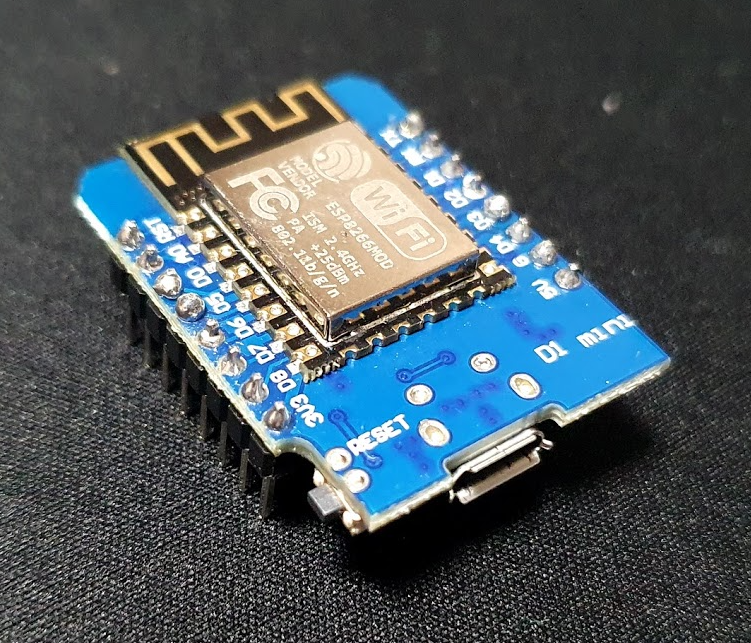
사용한 보드는 ESP8266기반에 ESP12E 모듈입니다. 정확하게는 wemos D1 mini로 USB 포트가 달려있어서 편리하게 사용할 수 있는 모델입니다. (ESP8266 모듈 아무거나 다 유사하게 사용할 수 있습니다.)
3.3V 레벨로 동작하는 시리얼 데이터를 사용한다면 추가적으로 회로를 구성할 필요 없이 모니터링하고자 하는 시리얼 단자와 Rx-Tx, Tx-Rx만 연결하면 되고 만약 5V 레벨의 데이터를 사용하고자 한다면 ESP12E의 Rx단자에 5V를 3.3V로 강하시켜줄 전압분배 회로만 구성해주면 됩니다.
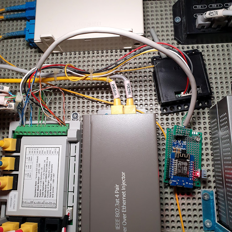
전 12V의 RS485통신 모니터링에 사용하기 위해서 5V/3.3V의 TTL신호를 12V로 변환시켜주는 RS485-TTL 변환 모듈을 준비해서 아래와 같이 연결했습니다. 여기서 변환 모듈의 A+, B+ 단자를 각각 신호를 읽어올 통신 단자에 연결해주면 되겠습니다.

준비된 보드를 USB에 연결하고 이제 소프트웨어 부분으로 넘어가겠습니다.
Software(펌웨어)
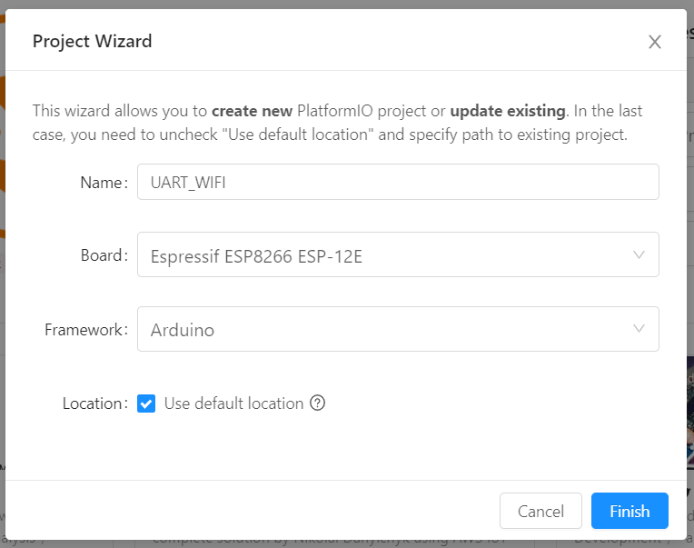
펌웨어 올려보겠습니다. IDE환경은 Visual Studio의 PlatformIO입니다. ESP-12E 보드용으로 새 프로젝트를 열어줍니다.
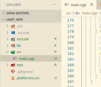
생성된 main.cpp파일을 열어서 아래의 소스코드를 복사하고 저장합니다. 38, 39, 40행의 정보만 본인의 환경에 맞게 수정합니다.
#include <Arduino.h>
// ESP8266 WiFi <-> UART Bridge
// by RoboRemo
// www.roboremo.com
// Disclaimer: Don't use RoboRemo for life support systems
// or any other situations where system failure may affect
// user or environmental safety.
#include <ESP8266WiFi.h>
// config: ////////////////////////////////////////////////////////////
#define UART_BAUD 9600
#define packTimeout 5 // ms (if nothing more on UART, then send packet)
#define bufferSize 8192
//#define MODE_AP // phone connects directly to ESP
#define MODE_STA // ESP connects to WiFi router
#define PROTOCOL_TCP
//#define PROTOCOL_UDP
#ifdef MODE_AP
// For AP mode:
const char *ssid = "mywifi"; // You will connect your phone to this Access Point
const char *pw = "qwerty123"; // and this is the password
IPAddress ip(192, 168, 0, 1); // From RoboRemo app, connect to this IP
IPAddress netmask(255, 255, 255, 0);
const int port = 9876; // and this port
// You must connect the phone to this AP, then:
// menu -> connect -> Internet(TCP) -> 192.168.0.1:9876
#endif
#ifdef MODE_STA
// For STATION mode:
const char *ssid = "SSID"; // Your ROUTER SSID
const char *pw = "password"; // and WiFi PASSWORD
const int port = 8899;
// You must connect the phone to the same router,
// Then somehow find the IP that the ESP got from router, then:
// menu -> connect -> Internet(TCP) -> [ESP_IP]:9876
#endif
//////////////////////////////////////////////////////////////////////////
#ifdef PROTOCOL_TCP
#include <WiFiClient.h>
WiFiServer server(port);
WiFiClient client;
#endif
#ifdef PROTOCOL_UDP
#include <WiFiUdp.h>
WiFiUDP udp;
IPAddress remoteIp;
#endif
uint8_t buf1[bufferSize];
uint16_t i1 = 0;
uint8_t buf2[bufferSize];
uint16_t i2 = 0;
void setup()
{
delay(500);
Serial.begin(UART_BAUD);
#ifdef MODE_AP
//AP mode (phone connects directly to ESP) (no router)
WiFi.mode(WIFI_AP);
WiFi.softAPConfig(ip, ip, netmask); // configure ip address for softAP
WiFi.softAP(ssid, pw); // configure ssid and password for softAP
#endif
#ifdef MODE_STA
// STATION mode (ESP connects to router and gets an IP)
// Assuming phone is also connected to that router
// from RoboRemo you must connect to the IP of the ESP
WiFi.mode(WIFI_STA);
WiFi.begin(ssid, pw);
while (WiFi.status() != WL_CONNECTED)
{
delay(100);
}
#endif
#ifdef PROTOCOL_TCP
Serial.println("Starting TCP Server");
server.begin(); // start TCP server
#endif
#ifdef PROTOCOL_UDP
Serial.println("Starting UDP Server");
udp.begin(port); // start UDP server
#endif
}
void loop()
{
#ifdef PROTOCOL_TCP
if (!client.connected())
{ // if client not connected
client = server.available(); // wait for it to connect
return;
}
// here we have a connected client
if (client.available())
{
while (client.available())
{
buf1[i1] = (uint8_t)client.read(); // read char from client (RoboRemo app)
if (i1 < bufferSize - 1)
i1++;
}
// now send to UART:
Serial.write(buf1, i1);
i1 = 0;
}
if (Serial.available())
{
// read the data until pause:
while (1)
{
if (Serial.available())
{
buf2[i2] = (char)Serial.read(); // read char from UART
if (i2 < bufferSize - 1)
i2++;
}
else
{
//delayMicroseconds(packTimeoutMicros);
delay(packTimeout);
if (!Serial.available())
{
break;
}
}
}
// now send to WiFi:
client.write((char *)buf2, i2);
i2 = 0;
}
#endif
#ifdef PROTOCOL_UDP
// if there’s data available, read a packet
int packetSize = udp.parsePacket();
if (packetSize > 0)
{
remoteIp = udp.remoteIP(); // store the ip of the remote device
udp.read(buf1, bufferSize);
// now send to UART:
Serial.write(buf1, packetSize);
}
if (Serial.available())
{
// read the data until pause:
//Serial.println("sa");
while (1)
{
if (Serial.available())
{
buf2[i2] = (char)Serial.read(); // read char from UART
if (i2 < bufferSize - 1)
{
i2++;
}
}
else
{
//delayMicroseconds(packTimeoutMicros);
//Serial.println("dl");
delay(packTimeout);
if (!Serial.available())
{
//Serial.println("bk");
break;
}
}
}
// now send to WiFi:
udp.beginPacket(remoteIp, port); // remote IP and port
udp.write(buf2, i2);
udp.endPacket();
i2 = 0;
}
#endif
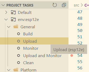
}PlatformIO 메뉴에서 Upload를 살포시 눌러서 펌웨어를 올려줍니다.
WiFi로 시리얼 연결
이제 모든 준비가 끝났으니 시리얼 데이터가 나오는 곳에 연결하고 전원을 넣어줍니다. 전원은 핸드폰 충전기를 이용해서 USB 포트에 꽂아주어도 되고 5V나 3.3V핀과 GND핀을 전원에 연결해도 되겠죠.
저는 요즘 아파트 홈네트워킹 패킷신호를 확인하는데 몰두를 하고 있는데요. 바로 이 홈네트워크의 RS485 통신 패킷을 읽어오기 위해서 아파트 통신반에 있는 RS485 입출력 단자에 연결해 보겠습니다.
결과 확인
시리얼 데이터는 PC에서 확인해 볼 텐데요. TCP 연결을 지원하는 시리얼 모니터링 프로그램이면 어떤 것이든 다 사용할 수 있습니다. 그런데 전 아파트 홈네트워킹 통신 패킷을 분석하기 위한 목적으로 시작했기 때문에 이 분야에서 아주 편리하게 사용할 수 있는 SerialPortMon이라는 공개 프로그램을 이용하였습니다.

연결을 해보면 신호가 아주 잘 들어오는 걸 볼 수 있습니다. ^^ 원래는 EW11이라는 RS485 신호를 WIFI와 연결해주는 부품을 사용해서 패킷을 수집하고 있었는데요. 실수로 이 부품을 태워먹어 급하게 대체할 방법을 찾다가 소스코드를 발견해서 시도를 해 봤습니다. 다행히 시행착오 없이 한방 해결이 되었네요. 간단히 만들어 볼 수 있는 와이파이 시리얼 모니터링 모듈이었습니다.
끝!
'Hardware > MCU(Arduino,ESP8266)' 카테고리의 다른 글
| ESP8266, Watchdog (wdt reset error) (4) | 2020.12.09 |
|---|---|
| 배터리를 사용하는 아두이노 프로젝트에 배터리 잔량 표시하기 (4) | 2020.12.07 |
| 전압 분배 회로 계산기 (0) | 2020.11.20 |
| wemos D1 mini 기본사양 (2) | 2020.11.10 |


댓글